Production Facilities
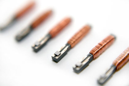
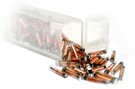
Installation system SAF03 for glass and ceramic fuses
The rotary clock SAF03 installs glass and ceramic fuses from a glass/ceramic body, two pre-tinned caps and a fusion wire.
A sand filling station can be switched on as an option.
The caps are fused using an inductive HF soldering process, so no flux or heating station is necessary.
Ultrasonic welding system USS01
On the USS01 welding machine, plastic parts are fully automatically welded together. The two articulated robots are equipped with ultrasonic welding tools, the welding process can be easily adapted to different components and converted.
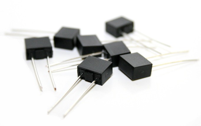
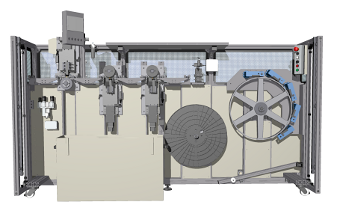
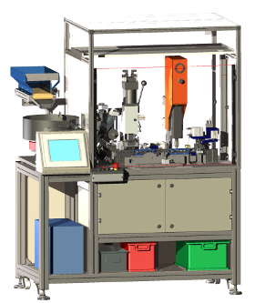
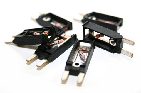
Mounting system for TR5 and TE5 fuses, type FAS01
With our FAS assembly systems, we present a newly developed, tin-free production process for TR5 and TE5 fuses, where production rates of up to 10,000 parts per hour are achieved.
The base parts of the fuses to be produced are automatically sorted into magazines and transported through the assembly sections via a linear transport system. A wire feeder inserts eight connecting wires into the base parts at the same time, after which the ends are flattened and shaped. The securing element is loaded and crimped in one piece for the 24 parts of a production magazine. A modern laser system fixes the connection wires, cuts the fuse element and solders the contact points. The soldering process is realized by a very cost-efficient, tin-free process.
At the end of the fuse assembly, each part is checked by a meter. The fuses then receive a sand-filled cap and are ejected from the production magazines. The empty magazines are automatically transported back to the filling station. The entire production area is protected by a light curtain.
The assembly process is monitored by two optical systems. The system itself is controlled by a powerful PLC, the laser and the vision systems are controlled by an integrated PC.
Flat fuse assembly line
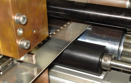
Skiving machine, type FES
Our FES Skiving Machine removes material up to a specified thickness from a zinc band. Each backup value is based on a specific thickness and shape of the fuse element. For this purpose, our FES Skiving Machine processes the zinc tape from which the safety elements will later be manufactured with three knives. The first one wears off a part of the top. The second wears larger portions of the material at the lower side The third cutter finally gives the tape the precise thickness. At the end of the process, the result is checked by a highly sensitive measuring device.
Punch for fuse elements, type FEP
Our FEP punches for the manufacture of securing elements produce an endless strip of securing elements at high speed and force. The FEP punching machines produce securing elements from an endless belt. The feed of the belt is realized by a servo drive. The punching tools can be easily exchanged in a short time, this is necessary to ensure a simple adaptation of the machine to many different types of security elements. The zinc tape is first processed in one of our skiving machines and then fed to the punch by a CWS unwinding unit. The resulting endless belt with punched safety elements continues to run into a CFA assembly system.
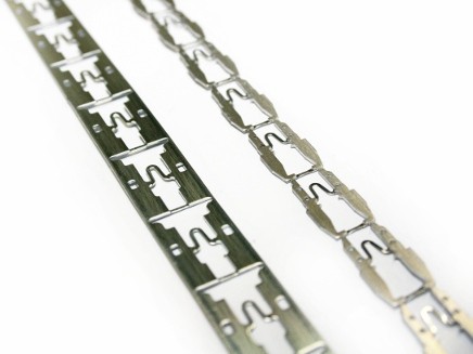
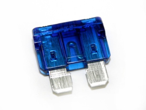
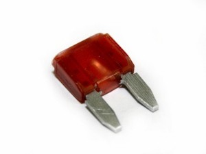
Mounting system for flat fuses, type CFA
Our mounting systems CFA for flat fuses manufacture, check and sort flat fuses of different types fully automatically. The fuse housing and the endless belt with the punched locking elements are fed to the CFA mounting system. A linear comb feed system developed for this purpose ensures that the individual fuses are transported through the machine. The housings are marked, then the securing element is fed, separated from the belt, aligned, fixed and welded. The finished fuses are checked at the following measuring station and, if necessary, sorted out. To make fuses for PCB applications, a pneumatic separator can optionally be activated, which shortens the connections of the fuses. Before the finished fuses are sorted into the good/bad boxes, the good parts will receive a weekly code that has been stamped on them.
Optimized sorting methods at the feeder and the time-efficient transport properties of the comb feed used can achieve production rates of 3,600 parts per hour and higher.
Assembly line for mini circuit breakers
Assembly machine for mini circuit breakers, type UWS
Our WFS system shapes and levels wires with very high precision. The system can be equipped with various tools for deforming the wires that are adapted to the respective application. The wire is fed via a coil, formed in the plant and wound up in new layers. Our standard system works with three deformation units that allow precise adjustment to the desired wire thickness at high throughput rates of up to 4m/min.
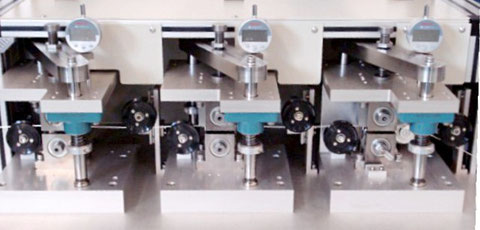
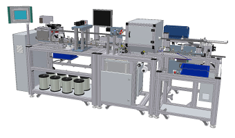
Assembly machine for mini circuit breakers, type UWS
The UWS system is a fully automatic assembly system for single-pole, thermal circuit breakers in mini design.
The system consists of an assembly table with 18 working units. The molded support plates are fed and loaded into the turntable and prepared. In the following stations, contact pads are cut from a supplied silver flat wire, placed on the support plates and welded. A welding inverter with a working frequency of 1kHz is used for this purpose. Subsequently, a resistor is used and fastened by two smaller welding units. The fully assembled circuit breakers are checked twice. On the one hand, a precise height measurement between the contact pad and the riveting is carried out on the housing, on the other hand, visual inspection is carried out with regard to the position of the resistance and for possible damage to the housing. Good parts are loaded into another turntable, where the connections are cut and the finished parts are sorted into a webbing. The system is controlled by a powerful PLC together with a PC. The welding process can thus be easily tracked and programmed.
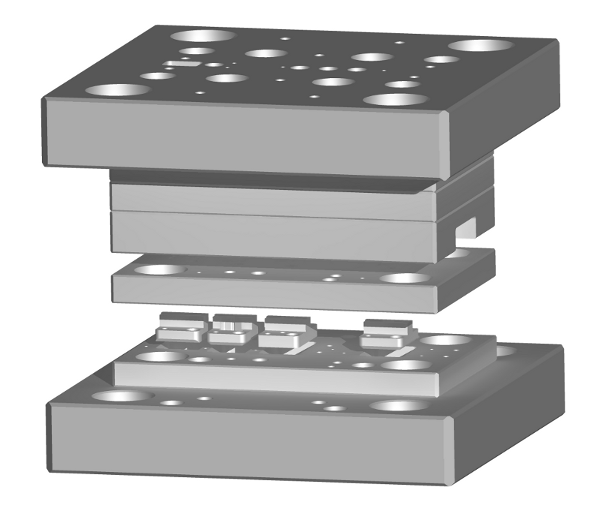
Welding unit for contact pads, type PWS
Our PWS welding unit is a punching extension unit for applying contact pads to the carrier material. In the manufacture of miniature circuit breakers, the WFS system wire forming and the contact pad welding in the UWS system can be replaced. The welding unit for contact pads PWS welds silver wire pieces onto a carrier material before it is pulled in by the punching machine. The wire is fed in programmable lengths via a stepper motor. The welding head is controlled by a servo drive and powered by an inverter power source. The entire system is synchronized with the punching machine.
Glass transponder assembly line
Transponder assembly line, type TAL
In the TAL transponder assembly line, transponder chips are placed and through structural bonding (adhesive bonding) contacted.
The unstocked tansponders are loaded into transport maggots by the packaging tape. The dosing system then puts an exactly dosed amount of adhesive on the unloaded transponders and the chips are placed from the wafer on the pads. The fully equipped transponers are hardened and measured.
Magazine mounter, type VLS
The VLS-Magazine Bearerer fills the production magazines of glass transponder production with glass tubes.
The glass tubes are transported to a sorting station where they are immediately aligned and transferred to the filling station. The production magazines are loaded from the input buffer via a linear axis, filled with glass tubes and transported to the output buffer. Input and output buffers each have a capacity of ten magazines and can be filled and emptied while the machine is running.
Dosing system, type MDS
The MDS dosing system fills glass tubes for transponder production with UV-curing adhesive.
The production magazines are clocked by a linear feed through the filling station. The dosing unit moves from a resting position to four adjustable filling positions along a servo axis and gives the selected amount of adhesive there. When a magazine is completely filled, it is transported into the light-tight output buffer.
UV hardener, type UVC
Our UVC hardener type UVC is a system for curing UV-sensitive substances.
The UV-sensitive parts are placed on the linear conveyor belt and pass through an outwardly sealed UV chamber at an adjustable speed. The UV irradiation within the chamber is activated by a sensor for the duration of the run.
Sealing system, type GSS
The GSS sealing system seals the assembled glass tubes using a micro burner.
An integrated system produces the gas for the micro burner. The production magazines are clocked by the burner unit. The burner unit moves down a precise adjustable stroke per glass tube and seals the rotating tubes. The burning time and a preheating time can be set on the control panel. The sealing process can be tracked via a monitor.
Transponder test & packaging system, TMS type
The TMS transponder test & packaging system measures, sorts and packs glass transponders to desired packaging units.
The finished transponders are transported individually to a sorting station via a feed system. There, the individual transponder is read by a reading antenna from a defined distance. Poor parts are sorted out, good parts are combined into programmable packaging units. An Excel file is generated from the data of the individual transponders, together with the lot data and the serial number of the packaging unit.
changing machines
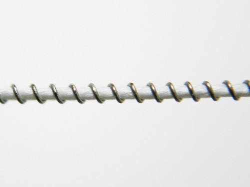
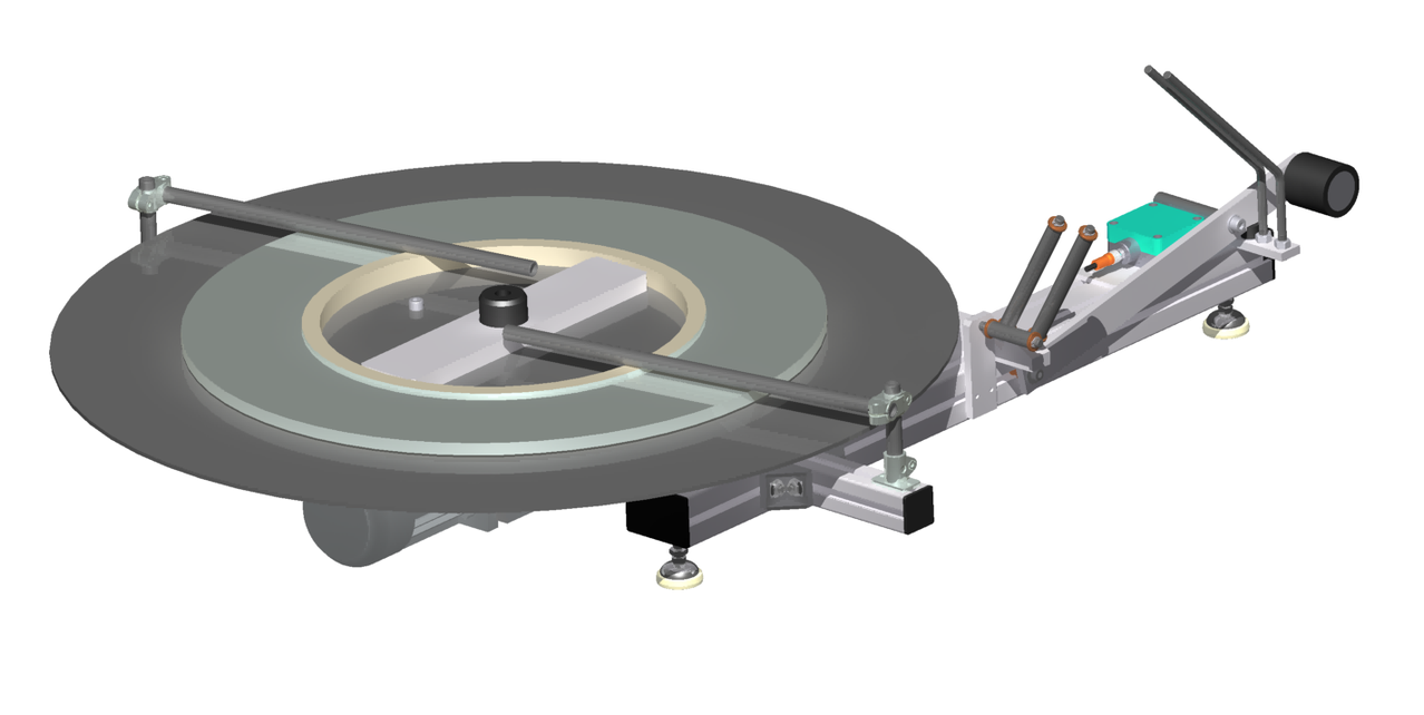
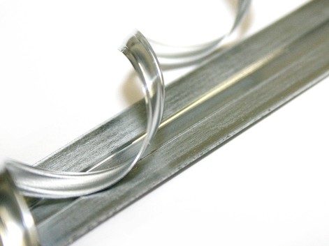
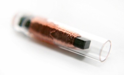
Automatic winding device, type FWS
Our FWS securing elements winding machine was designed to wrap endless, strap locking elements.
The glass to be wrapped is fed into the winding unit from below and wrapped in the wire with controllable speeds and gradients. A rotating coil unit detrolls the finished safety element. The system is adaptable to different diameters of silk and wire.
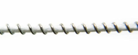
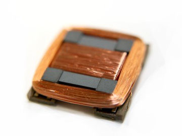
3D wrap system, type WA
The 3D wrap system type WA was designed to wind the axes of a 3D SMD transponder.
A 3D SMD transponder consists of a ferrite core with windings in all three spatial directions and in this way has optimal transmission and reception performance. Our 3D wrap system was designed to create such windings.